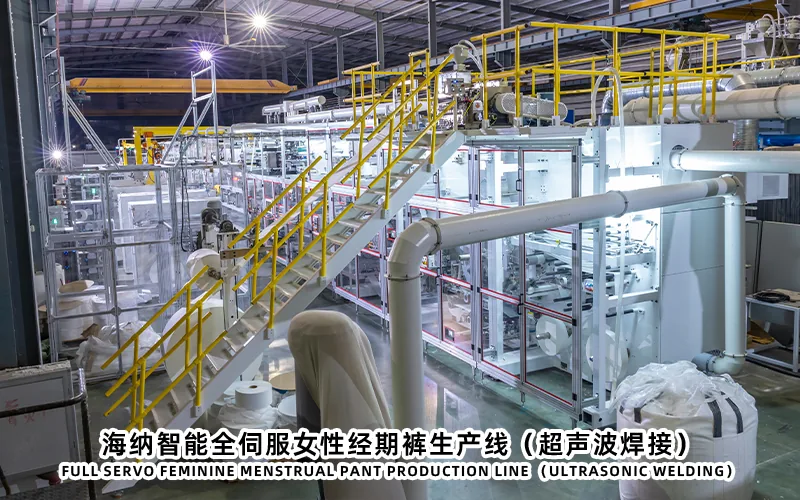
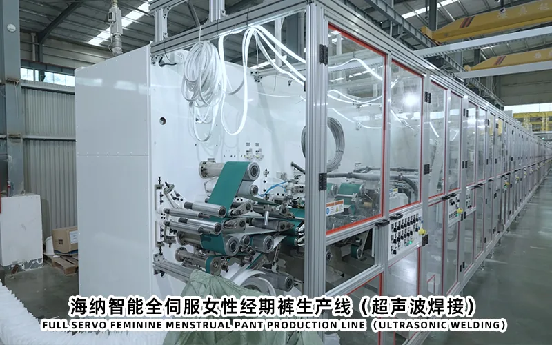
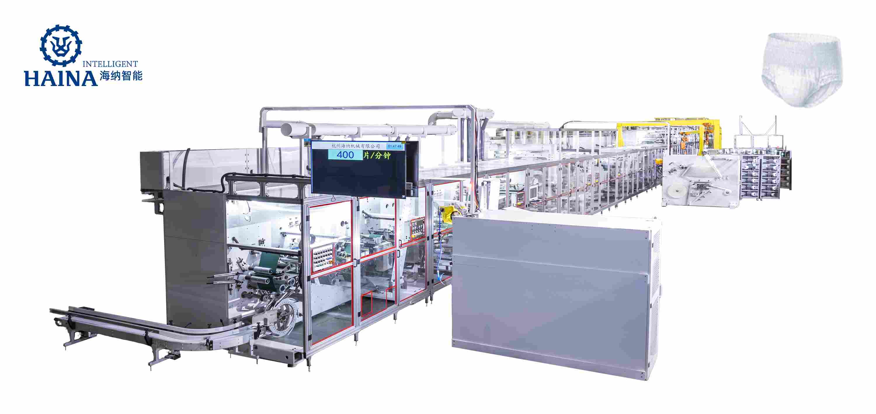
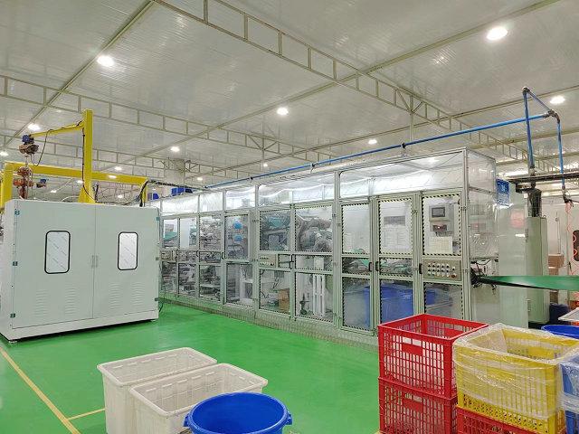
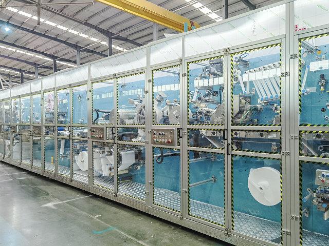
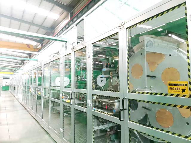
A female diaper making machine intended for menstrual pants needs coordinated control of the absorbent core, liquid-transfer layers, barrier features, elastic chassis, backsheet, and side joins. Core capacity alone does not prevent leakage. The line must place and contain the core consistently, preserve material integrity, maintain registration through speed changes and splices, and reject products with missing or displaced components. Buyers should define product drawings, material ranges, measurement methods, defect limits, and FAT challenge tests before selecting modules. Machine requirements should then be traced from each leak-risk path to a controlled process, inspection point, and accountable acceptance record.
Map the Complete Leak-Risk Path
Begin with the finished product and identify every route by which liquid could reach the edge or outer surface. The map normally includes topsheet intake, acquisition or distribution layers where specified, core absorption and spreading, core wrap, standing or inner barriers, leg opening contact, waist regions, backsheet continuity, side joins, and any cut or perforation close to the absorbent body. Each path creates a machine requirement.
Turn the product drawing into a registration stack. Use a common centerline and machine-direction reference to show core position, barrier position, elastic start and stop zones, leg-cut contour, backsheet boundary, body fold, side join, and final cutoff. State which dimensions are measured on the flat product and which are measured after elastic relaxation or conditioning. Otherwise, two teams may report different results from the same sample.
Define material and process responsibilities separately. The machine places, cuts, bonds, joins, and inspects materials, while the materials themselves supply absorption, fluid transport, elasticity, softness, barrier performance, and bond response. If a leak test fails, the investigation should be able to distinguish incorrect placement from an unsuitable material combination or test method.
The product drawing should connect every leak-risk zone to a converting station.
Control Core Formation and Distribution
The core system should be specified from the intended product structure. Document core length, width, contour, mass targets, distribution zones, wrapping, compression, and any layered construction. Record the supplied condition of fluff pulp and SAP, as well as approved alternatives. Do not assume that the same forming settings remain valid after changes in fiber, particle behavior, humidity, or supplier lot.
Review how pulp is prepared and conveyed, how air flow forms the core, how SAP is dosed, and how loose material is controlled. The process should minimize uncontrolled buildup while allowing cleaning and inspection. Ask where mass or feed deviations are detected and what happens after an alarm. A warning that does not identify and remove affected products leaves a quality gap.
Core uniformity needs a written measurement method. Total product mass cannot prove longitudinal or transverse distribution. Define sample conditioning, disassembly, sectioning, weighing, profile inspection, and permissible handling loss. If a core has different zones, collect measurements by zone. Preserve reference samples that demonstrate acceptable edge definition and distribution.
Design speed, stable working speed, normal operating speed, and FAT acceptance speed must remain separate. Air flow, dosing response, dust load, and core transfer can change as the line accelerates. Demonstrate quality at the agreed FAT condition and record the actual materials, environment, duration, and interruptions.
Transfer and Contain the Absorbent Core
A well-formed core can still cause leakage if it shifts, breaks, folds, or loses material during transfer. Review vacuum support, transfer timing, web speed matching, compression, wrapping, tissue integrity, and adhesive patterns. The core should enter the chassis without abrupt tension or impact that changes its profile.
Core containment is especially important near narrow crotch regions and leg contours. Identify the distance between the core edge and nearby cutting, bonding, or elastic features. Tooling tolerances, web wander, draw, and registration corrections can consume this margin. The buyer should define an alarm or reject condition before the core reaches an unacceptable position.
Splices and stops deserve separate trials. A splice can change thickness or web stiffness, while a stop can leave heated adhesive or compressed materials in one position. Specify how the machine tracks affected products through restart and how many products are quarantined. Test the recovery method instead of judging only steady-state samples.
Vacuum timing web support and containment preserve the core profile during transfer.
Coordinate Barriers Elastics and Leg Geometry
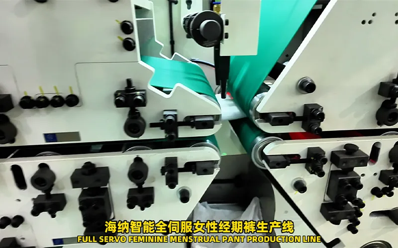
Barrier materials and elastic elements must be placed as a system. Record each barrier web width, fold, adhesive area, elastic count, elastic path, start and stop zone, and relation to the core. Define the finished-product measurement after a consistent relaxation and conditioning method. A raw feed ratio alone does not describe the resulting body fit.
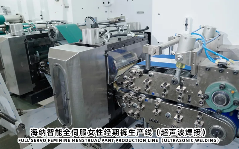
Leg contour cutting changes the geometry surrounding the core. The cutter, waste removal, web guiding, and elastic placement should remain synchronized. Poor waste extraction can pull a lightweight chassis sideways. Excessive vacuum or tension can distort a soft web. Review these settings with the actual material combination at several approved operating conditions.
Elastic break detection should identify the affected lane or element where practical, trigger a defined response, and support reject tracking. The quality plan should include missing elastic, displaced elastic, incorrect glue, exposed elastic, damaged barrier, and distorted leg opening. Challenge detection with controlled faults only under an approved safe procedure.
Engineering note: Leak protection should not be assigned to one station. Core position, barrier geometry, elastic recovery, leg cutting, web tension, and final fold can interact, so root-cause analysis needs synchronized machine and quality records.
Protect the Backsheet and Side Joins
The backsheet is the final material barrier and must survive unwinding, tension, lamination, cutting, folding, joining, and discharge. Document thickness, extensibility, surface treatment, roll quality, and approved tension range. Inspect for holes, wrinkles, contamination, edge damage, excessive draw, and adhesive strike-through. Handle thin or breathable films according to supplier data rather than copying a setting from another material.
Side joining creates the wearable form but can introduce local damage if energy, pressure, alignment, or material stack is wrong. Define the intended join appearance, strength test, opening behavior, edge feel, and defect categories. Inspect both sides because a common setting may produce different results if material tension or layer position is not symmetrical.
Folding devices should not force the core or barrier into a displaced position. Check guide surfaces, compression, timing, and clearance at startup, stable running, speed change, and restart. Sample products before and after folding to distinguish an upstream registration issue from downstream deformation.
HAINA can review the core, chassis, joining, and inspection scope of a menstrual pants production machine against buyer-supplied product and material definitions. Final requirements should be captured in approved drawings and a product-specific test plan.
Backsheet handling and side joining must protect the complete material stack.
Set an Inspection and Rejection Strategy
Inspection starts with a defect map, not a sensor shopping list. For every critical defect, specify the process cause, observable signal, inspection location, response, reject mechanism, and verification method. Some properties can be checked online, while core distribution, bond strength, absorbency, and fit may require offline sampling. The plan should combine both.
Online inspection may review presence, position, continuity, or registration depending on the installed system and product contrast. Confirm resolution, field of view, lighting, recipe control, calibration, data retention, and false reject handling. A detected error must remain associated with the correct product until physical rejection is confirmed.
Offline sampling should have a frequency tied to startup, stable production, material splice, size change, maintenance, and alarm recovery. Record machine recipe, material lots, operator, sample position, and result. If a defect is found, define the quarantine window and release authority.
Use a Core and Leak-Protection Requirement Matrix
Product function
Machine control point
Acceptance evidence
Failure investigation
Absorbent distribution
Pulp preparation SAP dosing air forming compression
Sectioned core measurements and run record
Material feed air balance buildup or recipe drift
Core location
Transfer timing vacuum web guiding registration
Flat-product position measurements
Draw tension sensor timing or transfer support
Barrier continuity
Web feed fold adhesive and position control
Visual inspection and approved functional test
Material defect web wander fold or bonding
Leg seal and fit
Elastic feed leg cut waste removal chassis alignment
Relaxed dimensions and component presence
Elastic break recovery cutter or web distortion
Outer containment
Backsheet tension lamination folding and side join
Integrity join and opening checks
Film damage contamination energy or pressure
Add owners and records to the matrix. Product development approves construction, quality approves methods, operations controls routine settings, maintenance owns calibration and mechanical condition, and the supplier demonstrates the agreed equipment functions. This makes leak-risk control transferable after commissioning.
Prove the Requirements During FAT
Core and leak-protection FAT sheet
Confirm approved drawings materials material lots and product recipes.
Inspect pulp SAP core wrap adhesive barrier elastic and backsheet threading.
Record startup acceleration stable operation planned stop and restart samples.
Measure core distribution position barrier placement elastics leg geometry and joins.
Challenge agreed alarms inspection and reject tracking under safe conditions.
Separate setup waste process rejects inspection rejects and downstream losses.
Run each launch size and complete one representative controlled changeover.
Archive samples recipes data sheets defect logs and unresolved action owners.
Do not approve a line only because a short sample looks correct. Agree the run duration and sampling plan in advance, and document every stop. A sustained test should show whether core systems, dust collection, adhesive application, tension control, joining, and inspection remain stable as operating conditions change.
Functional liquid testing should use an approved method that defines dosing, location, timing, conditioning, loading, measurement, and pass criteria. The method must suit the product and should not be invented during FAT. Where full laboratory testing cannot be completed at the machine factory, agree which dimensional and construction evidence is accepted at FAT and which tests are completed at site before final release.
Acceptance records should link product results with settings materials stops and inspection responses.
Frequently Asked Questions
Can a heavier absorbent core solve every leakage problem?
No. Leakage can also result from poor intake, displaced core, damaged barriers, leg gaps, backsheet defects, side-join damage, or unsuitable fit. Investigate the complete product system.
Which core measurements should be recorded during FAT?
Use the approved plan for total and zoned mass, length, width, contour, position, integrity, and any specified distribution method, with materials and machine conditions recorded.
Is online vision enough to approve leak protection?
No. Vision can verify selected visible presence and position features, but offline tests are still needed for core distribution, bonding, integrity, absorption, and other functional properties.
How should splice products be managed?
Define how the line detects each splice, tracks the affected product window, rejects or quarantines it, and proves recovery before accepted output resumes.
Conclusion
Core and leak protection on a female diaper making machine depend on a chain of controlled functions. Define the product geometry and materials, form and transfer the core consistently, coordinate barriers with elastic and leg cutting, protect the backsheet and joins, and connect inspection to confirmed rejection. A requirement matrix and product-specific FAT turn these interactions into measurable evidence. This gives the receiving factory a stronger basis for setup, troubleshooting, quality release, and future material changes.