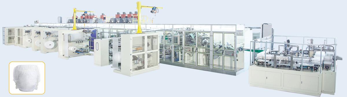
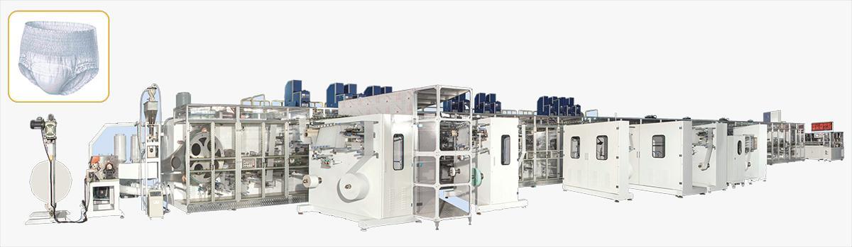
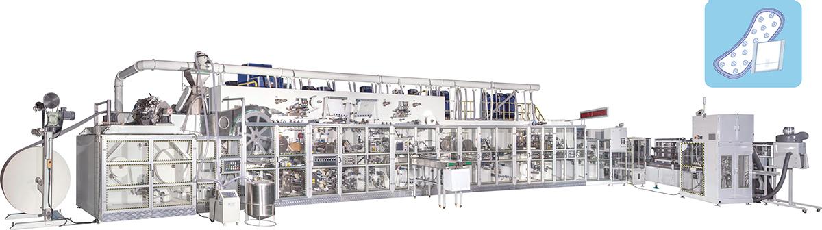
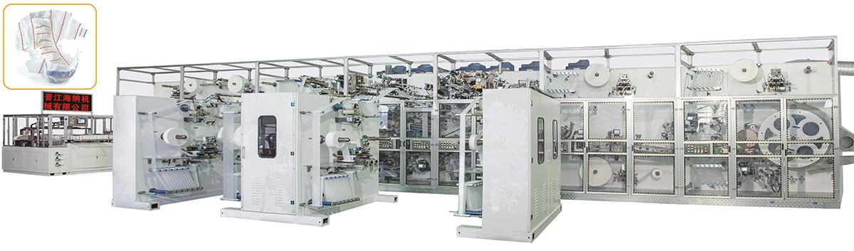
Utility requirements for a diaper manufacturing production line should be engineered from an approved equipment layout and operating sequence, not copied from one total on a quotation. The plant must define electrical supply and power quality, compressed air, vacuum and dust extraction, adhesive heating, cooling or ventilation, network connections, lighting, and environmental conditions by process zone. For each utility, separate connected load, peak demand, expected operating demand, quality limits, connection location, isolation, measurement, and future allowance. The final design depends on line modules, raw materials, packing automation, local climate, building rules, and recovery strategy. Supplier data and buyer calculations must be reconciled before installation.
Build a Zone Based Utility Register
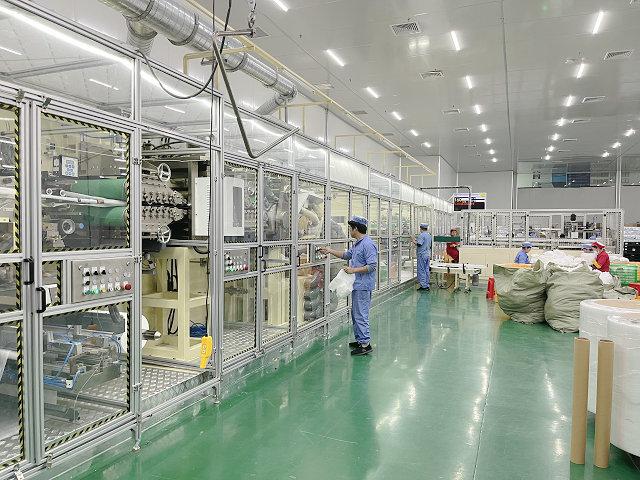
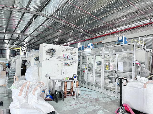
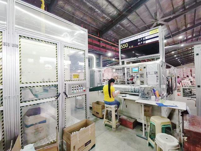
Divide the line into material preparation, unwinding, core formation, converting, adhesive application, inspection, discharge, auto packing, and supporting areas. For each zone, list every utility consumer and the physical connection point. Include equipment supplied by third parties. This exposes loads that may be missing from a single machine total, such as adhesive melters, extraction fans, compressors, chillers, coders, inspection cabinets, and baggers.
Record connected rating, normal operating estimate, peak or starting condition, allowable variation, required cleanliness, exhaust or return path, isolation device, measurement point, and data owner. Keep provisional supplier data visibly marked until approved drawings are issued. A total without the underlying consumers is difficult to verify and cannot guide distribution design.
Create load cases for startup, stable production, product changeover, cleaning, planned shutdown, and loss of one service. Some consumers run continuously while others cycle or start together. The plant engineer should calculate diversity and distribution from the sequence rather than assuming that all nameplate ratings occur continuously.
Give the register revision control and a named owner. Supplier electrical, mechanical, adhesive, extraction, and packing data may arrive at different design stages. The owner should reconcile units, reference conditions, simultaneous-demand assumptions, and connection coordinates before releasing site work. Record why an allowance changes so the plant can distinguish an approved equipment revision from a calculation correction.
Zone-based utility planning links every consumer to a real location and operating condition.
Plan Electrical Supply and Power Quality
Confirm site voltage, frequency, phase arrangement, grounding method, available fault level, and permitted harmonics or disturbances with qualified local engineering. Compare these conditions with the final equipment electrical schedule. Identify whether transformers, voltage conditioning, harmonic treatment, surge protection, or controlled backup is required. Such devices should be selected from measured or engineered conditions, not added by habit.
Separate main machine power from adhesive systems, vacuum or extraction, compressed-air equipment, cooling, packing machines, laboratory loads, and room services. Show distribution panels, cable routes, protective devices, local isolators, emergency interfaces, and lockout points. Confirm that cable sizing accounts for route, grouping, temperature, installation method, and local requirements.
Decide what must happen during a voltage dip or power loss. The line may stop immediately, maintain control power long enough to save state, protect heated adhesive, or follow another agreed sequence. Define restart checks and product disposition. Backup power does not need to keep the entire line producing to have value; it may support controls, data, or a safe shutdown.
Plan energy measurement by useful boundary. Main distribution readings show total demand, while selected submetering can separate converting, vacuum, extraction, adhesive, air, and packing. A baseline should identify product, operating rate, active modules, and environmental condition. These records support troubleshooting and cost analysis without claiming that one short test represents every production condition.
Size Compressed Air for Demand and Quality
Request air consumption by pressure level and operating state, including normal demand, simultaneous peaks, cleaning restrictions, and downstream packing. State air quality requirements for moisture, oil, and particles at the equipment connection. The plant system may need compression, drying, filtration, storage, distribution, and point-of-use treatment.
Pressure at the compressor does not prove pressure at the machine. Calculate pipe losses through distance, diameter, fittings, filters, regulators, and peak flow. Install measurement where it can reveal the condition seen by the equipment. A stable pressure reading at low demand may hide a drop during repeated cylinder motion or bagger cycles.
Define isolation and condensate management. Arrange distribution so one maintenance action does not unnecessarily stop unrelated equipment. Pneumatic exhaust, leaks, and inappropriate use of compressed air for cleaning can add noise, contamination, and cost. Include a leak inspection route in routine maintenance.
Review receiver and compressor control behavior with the demand profile. A system that meets average consumption can still cycle poorly or lose pressure during coincident movements. Check whether a local receiver, larger branch, staged compressors, or control adjustment is justified through calculation and measurement. Avoid adding equipment before the actual restriction has been located.
Pressure, quality, and peak demand must be verified at the equipment connection.
Design Process Vacuum and Dust Extraction
Process vacuum may hold, transfer, form, or position materials, while dust extraction removes airborne fiber and process waste. Treat these as defined systems even if they share fans or duct areas in a proposed design. Identify each pickup, required flow or pressure, filter, separator, waste container, fan, damper, and discharge point.
Duct design must consider simultaneous demand, branch balance, pressure loss, cleanout access, wear, condensation risk, noise, and fire or environmental requirements. Long flexible ducts added after machine installation can reduce performance and obstruct maintenance. Coordinate fixed ducts, cable trays, lighting, sprinklers, cranes, and service doors in elevation as well as plan view.
Agree who supplies machine connections, flexible joints, main headers, supports, filters, fans, exhaust stacks, and building penetrations. Define filter inspection and differential-pressure monitoring where applicable. During commissioning, measure performance at representative branches and observe product behavior, not only fan operation.
Manage Adhesive Heat Ventilation and Environment
Hot-melt systems add electrical load and heat near material webs and operators. List melters, heated hoses, applicators, exhaust needs, temperature zones, warm-up sequence, and shutdown practice. Place equipment so filters, tanks, hoses, and nozzles can be serviced safely without contaminating product areas or blocking aisles.
Room temperature and humidity can affect materials, static behavior, adhesive response, operator comfort, and electrical cooling. Define acceptable equipment ambient conditions from approved supplier data, then compare them with local seasonal conditions and internal heat gains. Include ventilation or air-conditioning loads from motors, cabinets, adhesive, people, lighting, and the building envelope.
Raw-material storage and production conditions should be coordinated. A roll moved from a very different environment may require controlled acclimation. Keep doors, air discharge, dust sources, and direct sunlight from creating localized conditions at sensitive unwinds or inspection cameras.
Heat sources, cabinet cooling, airflow, and material conditions belong in one environmental plan.
Route Utilities Without Blocking Access
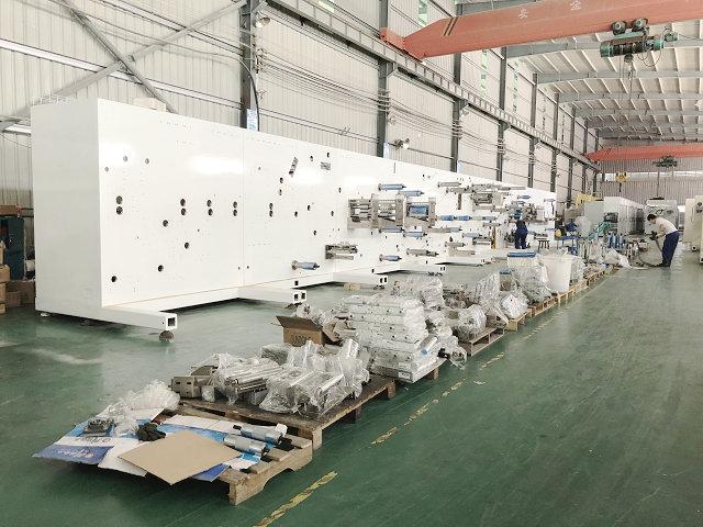
Overlay utility routes on the full machine working envelope. Show guard opening, roll loading, operator positions, cleaning access, blade or roller removal, electrical cabinet doors, change-part carts, and lifting paths. A connection can be technically correct yet make routine work unsafe or slow.
Use defined elevations and supports for cable trays, air pipes, vacuum ducts, cooling lines, and network routes. Protect crossings from forklifts and material carts. Avoid unsupported hoses across floors and avoid placing isolation valves where a stopped machine must be entered to reach them. Label services and flow direction consistently.
Reserve expansion only for identified future needs. An oversized main header can be reasonable if a documented second line is planned, but unused branches should remain isolated and clean. Future capacity also requires electrical panel space, building access, extraction capacity, compressor margin, and maintenance space, not just an empty floor rectangle.
Assign Every Utility Interface
Draw a battery limit around the supplied equipment and label each connection. Record utility type, condition, size, direction, physical location, supplier deliverable, buyer deliverable, third-party work, test method, and approval owner. Include network and remote-support connections as well as physical services.
For project review, HAINA can provide machine-side data and connection information for the selected automatic baby diaper manufacturing machine. The buyer's qualified engineers remain responsible for adapting distribution, protection, building services, and local compliance to the actual site. This responsibility split should be written into the project schedule.
Update the interface register when layouts or modules change. Adding an auto bagger, different adhesive system, or larger extraction unit can alter loads and routes. Do not wait until installation to reconcile revisions.
Utility commissioning should produce a handover pack containing approved schematics, settings, test records, baseline readings, filter and treatment details, isolation locations, spare recommendations, and maintenance tasks. Train both production and facilities teams on abnormal conditions. The machine technician may see unstable pressure at a station while the utility technician sees only a normal compressor panel; shared reference data helps them diagnose the same event.
Use a Utility Design Decision Table
Utility
Supplier data
Buyer engineering
Site verification
Electrical
Consumers, ratings, starting behavior, quality limits, and connections
Distribution, protection, cables, grounding, conditioning, and backup
Voltage, phase, grounding, loading, and stop-restart test
Compressed air
Pressure, quality, normal and peak consumption, and connection
Compressor, dryer, storage, headers, drops, and isolation
Pressure and quality at peak machine demand
Vacuum and extraction
Pickup requirements, branches, filters, and machine boundary
Headers, fans, exhaust, supports, waste route, and building work
Branch measurements and process observation
Environment
Permitted ambient range and equipment heat sources
Ventilation, cooling, humidity, room balance, and storage
Conditions across shifts and seasonal risk review
Network and data
Ports, protocols, remote support, and machine records
Secure network, access approval, retention, and backup policy
Connection, permissions, recovery, and access log
Test Site Readiness Before Commissioning
Pre-start utility checks
Confirm approved drawings, connection labels, isolation, guarding, and physical access.
Clean and inspect new air, vacuum, extraction, and cooling routes before connection.
Verify voltage, phase, grounding, protective settings, and cabinet environmental conditions.
Measure compressed-air pressure and quality during a representative peak-demand test.
Check extraction branches, filters, waste collection, direction, vibration, and noise.
Test utility-loss response and controlled restart with agreed product disposition.
Record baseline readings at stable production for future maintenance comparison.
Baseline utility measurements should be captured under a documented production condition.
Production Line Utility FAQ
Can the quoted total power be used to size the factory transformer?
Not alone. Qualified engineers must consider all consumers, operating and starting cases, diversity, expansion, power quality, distribution losses, and local design requirements.
Why measure compressed air at the machine?
Header pressure may remain acceptable while filters, long pipes, fittings, or peak flow create a damaging pressure drop at the actual connection.
Are vacuum and dust extraction the same utility?
They can share equipment in some designs, but their process purpose, pickups, flow, filtration, waste, and verification requirements should be defined separately.
When should final utility data be frozen?
Freeze it after the equipment configuration and layout are approved, then control every later module or site change through the interface register.
Conclusion
Reliable utilities come from a zone-based consumer register, approved machine data, and site engineering that considers operating events and real routes. Define quality and responsibility at every connection, preserve maintenance access, test peak conditions, and record commissioning baselines. This approach gives a diaper manufacturing production line stable support without confusing equipment ratings with complete factory design.