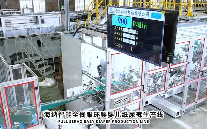
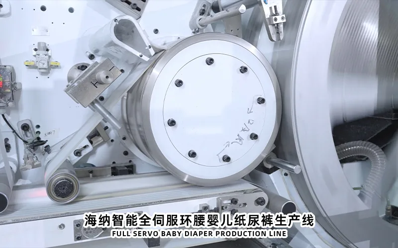
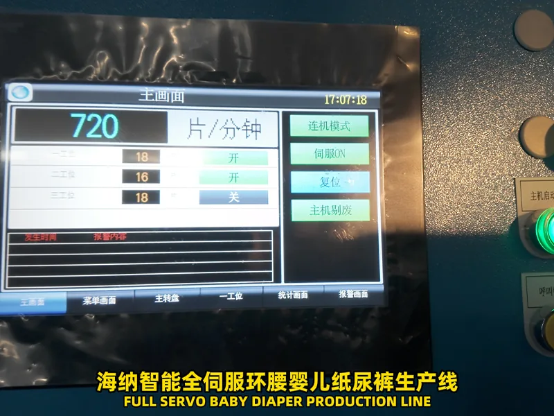
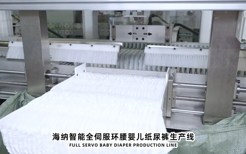
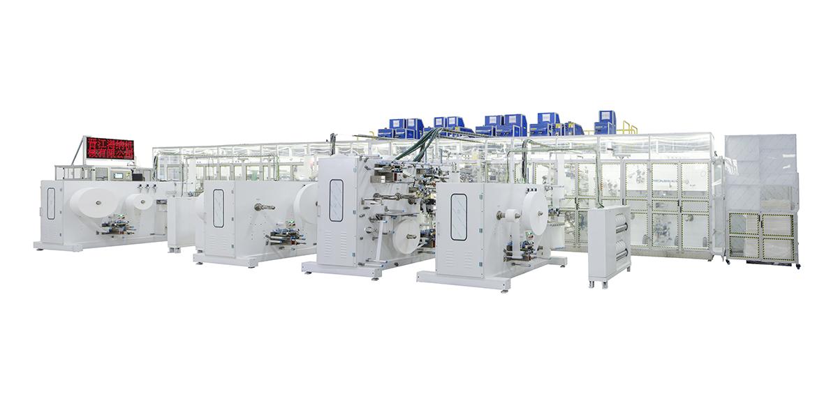
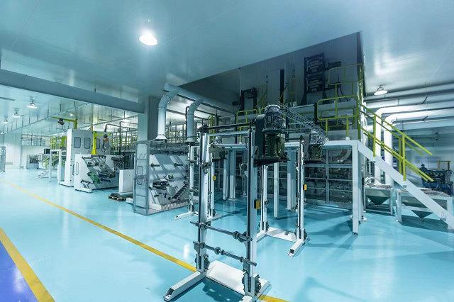
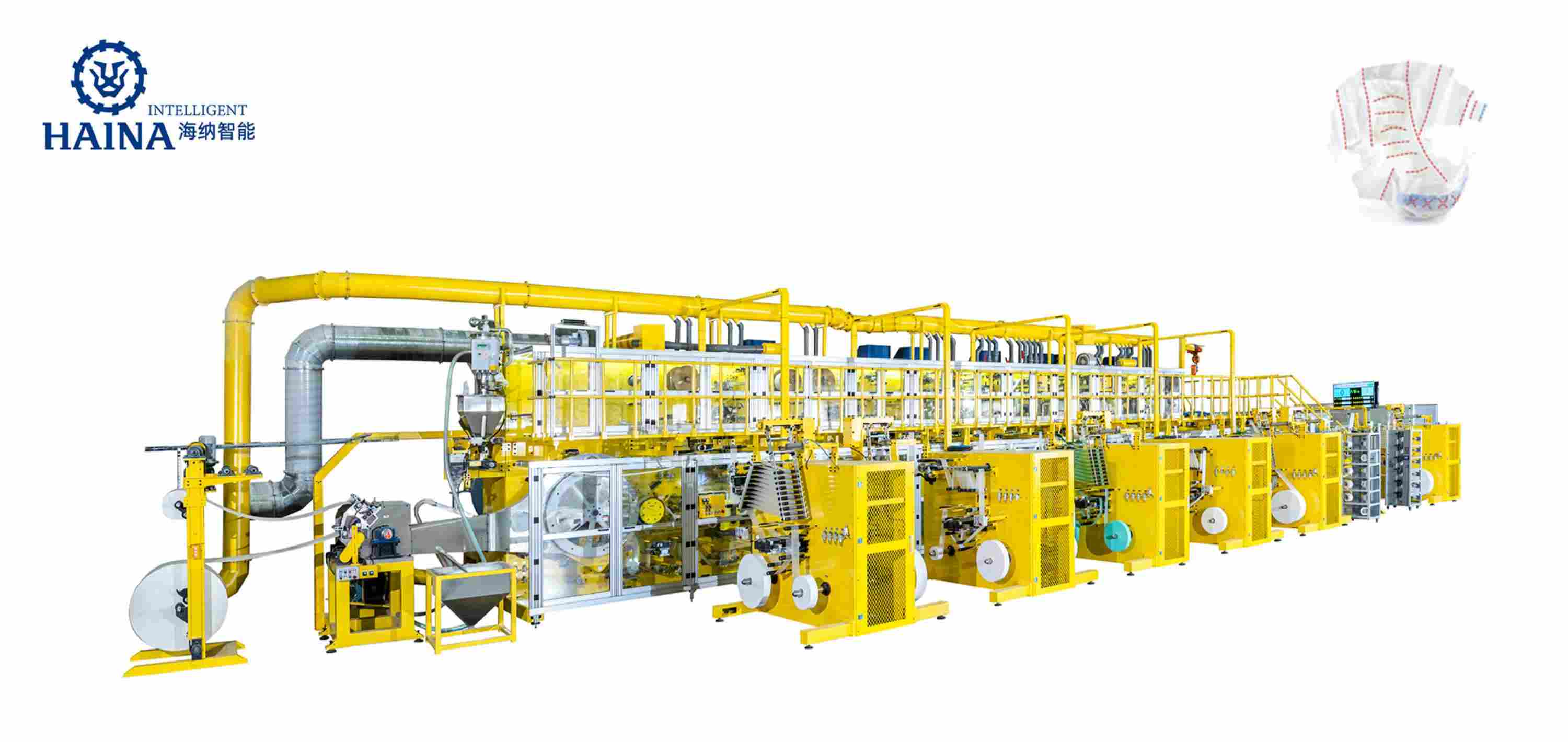
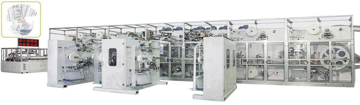
Servo drive and mechanical drive are not simply modern and old choices in diaper manufacturing equipment. A servo axis is useful where independent electronic position control, recipe adjustment, registration correction, or controlled acceleration creates measurable process value. A mechanical transmission can remain practical where several elements must keep a fixed relationship and a simple, robust drive train is easier to maintain. Buyers should compare the drive architecture zone by zone, including web feeding, core formation, cutting, elastic application, folding, transfer, and packaging. The correct decision depends on product range, changeover needs, maintenance skills, spare parts, control integration, and acceptance testing.
Define the Drive Architecture Before Comparing Labels
A quotation may describe a machine as full servo, servo controlled, or mechanically driven, but those labels do not reveal which functions are independently controlled. Ask for a functional drive list. It should identify every main motor, servo motor, gearbox, shaft, timing belt, electronic cam, encoder, registration sensor, dancer, tension controller, and synchronized packaging interface. The list should connect each component to a process zone and explain how that zone follows line speed.
Separate the power source from the motion relationship. A servo motor can drive a mechanically linked group, while a conventional motor can feed a section whose final position is corrected elsewhere. Likewise, replacing a line shaft with several motors does not automatically improve product quality. The value comes from the control logic, feedback devices, mechanical stiffness, tuning, and repeatability of the whole motion chain.
Buyers should also distinguish a recipe setting from closed-loop correction. A recipe may load a target phase or speed ratio, but a sensor and control loop are needed when the machine must detect and correct real web movement. Request a drive architecture drawing and a plain-language sequence description before comparing suppliers. This prevents a broad marketing term from hiding different equipment scopes.
Drive comparison should begin with the relationship between converting zones rather than a single machine label.
Where Servo Control Creates Process Value
Servo control is most valuable where one process position must be adjusted independently while remaining synchronized with the master line reference. Typical examples can include material feeding, rotary cutting, patch placement, waistband or tape application, product transfer, folding, and stack delivery. The exact selection depends on the product construction and the supplier design, so the buyer should ask what variable each servo axis controls.
Electronic gearing allows a controlled speed ratio or phase relationship to be changed through the control system. This can support recipe-based size changes and fine registration adjustments without exchanging every mechanical transmission component. Electronic cams can coordinate nonuniform motion where a mechanism must accelerate, dwell, or return through a defined cycle. These functions are useful only when sensor feedback, axis capacity, and mechanical response are suitable for the task.
A servo system can also make diagnostics more visible. The control platform may expose following error, torque trend, axis state, alarm history, or position deviation. Maintenance staff can use that information to separate a control issue from friction, loading, web tension, or a damaged mechanical component. Buyers should confirm which data are shown on the HMI, how trends are retained, and whether technicians receive backup and recovery procedures.
Buyer note: Count useful controlled functions, not motors. An additional axis has value only when its purpose, feedback, adjustment range, alarm response, and FAT method are documented.
Where Mechanical Drive Can Remain Practical
Mechanical drive can be appropriate where elements need a permanent fixed relationship and frequent independent adjustment is unnecessary. Gears, shafts, chains, and timing belts provide a visible transmission path that many maintenance teams understand well. In a stable product program with limited size variation, a correctly designed mechanical group can avoid unnecessary control complexity.
The tradeoff is that phase changes may require manual adjustment, exchange parts, or machine stoppage. Wear, backlash, belt condition, lubrication, alignment, and shaft loading can affect timing. A long mechanical transmission may also carry disturbances between zones. These are not reasons to reject the design automatically; they are reasons to inspect component selection, access, guarding, adjustment methods, and preventive maintenance.
Ask how a mechanical section is referenced after parts are removed. Timing marks, setting gauges, documented tooth positions, torque values, and reassembly procedures reduce dependence on individual technician memory. Confirm whether critical gears or belts are standard purchased components or supplier-specific parts. A practical architecture should match the plant's ability to inspect, lubricate, align, and replace the transmission.
Mechanical accessibility and reference methods are part of the drive decision.
Compare Registration Web Tension and Cut Position
Registration problems are often blamed on the drive type even when the root cause is upstream. Material roll variation, unwind braking, splice quality, dancer movement, web guiding, vacuum stability, adhesive behavior, elastic tension, sensor contrast, and product slip can all change the position seen at a cutter or applicator. A drive system cannot correct a disturbance that is not measured or that exceeds the available control range.
Map the control chain for every critical feature. Identify the reference mark or edge, sensor location, measured error, correction axis, response limit, and reject logic. Then ask what happens during acceleration, deceleration, roll change, splice passage, and restart. The answer should describe the process response, not only state that registration is automatic.
During sample evaluation, measure the finished feature relative to its intended product reference. Do not rely only on an HMI position value. A stable screen value can coexist with product movement if the web slips after measurement. Compare trends across accepted production, planned stops, material changes, and speed changes. This makes the drive assessment part of a complete process study.
Review Changeovers Recipes and Operator Work
Electronic recipes can reduce repeated entry of position, ratio, temperature, tension, and timing settings. They can also create risk when values are incomplete, unprotected, or copied without validation. Request a recipe parameter list for every planned product size. The list should show which settings load automatically, which require physical change parts, which need operator confirmation, and which remain adjustable during production.
Walk through one representative changeover from the last accepted product to the first accepted product in the new size. Record shutdown steps, tooling exchange, web threading, servo homing, mechanical indexing, sensor adjustment, adhesive setup, recipe selection, trial material, inspection, and release. The useful measure is not only elapsed time. Also record the number of manual interventions, discarded products, adjustments, and quality checks.
Access control matters. Operators may need limited process adjustment, while engineering staff control deeper axis and cam settings. Confirm user levels, change records, backup methods, and recovery after a power interruption or control replacement. A well-planned interface keeps normal correction available without making critical synchronization values easy to alter accidentally.
Recipe design should connect electronic settings with physical change parts and quality checks.
Plan Maintenance Diagnostics and Spare Parts
Servo equipment changes the maintenance skill mix. Technicians need to interpret axis alarms, encoder feedback, communication status, drive parameters, motor cables, and mechanical load. They also need controlled copies of programs, drive settings, HMI recipes, and network configuration. Mechanical systems require disciplined inspection of lubrication, backlash, tension, alignment, bearings, couplings, keys, and guards. Both architectures still contain mechanical wear points.
Review spare parts by failure consequence and recovery time. For servo sections, consider the interchangeability and setup requirements of drives, motors, encoders, cables, communication modules, and feedback devices. For mechanical sections, consider gears, timing belts, chains, bearings, couplings, seals, and special shafts. The buyer should know whether replacement requires software loading, parameter transfer, mechanical timing, or supplier assistance.
Ask the supplier to demonstrate a controlled backup and restore process during training. For the HAINA automatic baby diaper manufacturing machine, buyers can use their proposed product matrix and plant maintenance capability to discuss which controlled functions and service documents belong in the project scope. Final drive allocation should appear in approved technical documents rather than remain an informal sales description.
Use a Zone by Zone Drive Decision Table
Decision variable
Servo-oriented evidence
Mechanical-oriented evidence
Buyer verification
Independent position change
Axis purpose, feedback, correction logic, and adjustment limits
Documented manual phase method or exchange parts
Test the planned product change
Fixed synchronization
Electronic gear reference and fault response
Transmission drawing, backlash control, and timing marks
Inspect repeatability after stop and restart
Registration control
Sensor, measured error, correction axis, and reject logic
Stable fixed geometry with upstream web control
Measure finished products across operating events
Maintenance recovery
Diagnostics, backups, replacement setup, and trained support
Access, alignment tools, lubrication, and spare transmission parts
Simulate one representative replacement
Changeover work
Validated recipes plus required physical actions
Clear indexing, tooling, and setting procedures
Record time, interventions, waste, and quality release
The table should be completed for actual process zones rather than for the line as a whole. Procurement can then compare scope, production can review operator effort, maintenance can assess recovery, and quality can define product measurements. This turns a broad technology comparison into a traceable equipment decision.
Verify the Selected Architecture During FAT
Drive FAT checklist
Match installed motors, drives, sensors, gearboxes, and transmission parts to the approved list.
Confirm axis names, master references, homing sequences, user levels, and alarm messages.
Run approved materials through acceleration, steady production, controlled stop, and restart.
Measure critical product positions instead of relying only on displayed machine values.
Perform the agreed size or format change and record every electronic and mechanical action.
Review fault response for a sensor loss, communication alarm, drive trip, and power recovery where safe.
Verify program, parameter, recipe, and drawing backups and demonstrate one restore procedure.
Confirm spare parts, special tools, maintenance instructions, and training records before shipment release.
FAT should connect the documented drive architecture to measured product results.
Frequently Asked Questions
Does more servo control always mean better diaper quality?
No. Quality depends on materials, web handling, sensing, mechanics, tuning, process settings, and inspection as well as drive type. Each axis should have a defined control purpose and verification method.
Can a mechanically driven line support several diaper sizes?
It can, but buyers should examine the required exchange parts, manual phase settings, threading changes, adjustment time, trial waste, and release checks for the planned size matrix.
What documents should describe a servo architecture?
Request a drive list, functional description, electrical drawings, axis and alarm list, recipe parameters, backup files, replacement procedures, spare parts list, and training scope.
How should buyers compare maintenance cost without supplier claims?
Compare installed component quantities, accessibility, inspection tasks, spare prices, setup requirements, expected recovery steps, local technical skills, and supplier response terms. Use the same failure scenarios for every quote.
Conclusion
Servo and mechanical drive decisions should be made at process-zone level. Define the required motion, correction, changeover, diagnostic, and recovery function before selecting the architecture. Then verify sensors, mechanical transmission, recipes, access, backups, spare parts, and finished-product results during FAT. This method gives buyers a clearer basis for comparing diaper manufacturing equipment than counting servo motors or accepting a broad machine label.